

The diesel engine assembly process is a highly systematic and technically rigorous operation that must be carried out in strict accordance with standard sequences and process specifications to guarantee engine performance, reliability and service life. The following core procedures are summarized based on industrial standards and actual assembly line operations:
I. Pre-assembly Preparation
1. Environment and Tool Preparation
Assembly shall be performed in a clean, dust-free workshop to prevent impurities from entering engine internals.
Prepare special tools: cleaning machines, torque wrenches, bearing presses, oil seal installers, clearance gauges, etc.
2. Parts Inspection and Treatment
Conduct visual and dimensional inspection on all components (cylinder block, crankshaft, pistons, connecting rods, camshafts, etc.) to confirm no damage, deformation or excessive wear.
Thoroughly clean all parts with detergent and blow dry using compressed air; pay special attention to cleaning critical oil galleries.
Group pistons and connecting rods by weight to control the allowable weight difference of cylinder assemblies on the same engine and ensure dynamic balance.
II. Basic Component Assembly
1. Cylinder Block Preprocessing
Place the cylinder block with its bottom face downward for feeding, secondary cleaning and air blowing, then stamp the engine model and serial number.
Rotate the block 180°, verify the serial number, and position it with the bottom face upward for subsequent assembly.
2. Main Bearing and Crankshaft Installation
Fit upper and lower bearing shells into the cylinder block and main bearing caps, aligning all oil holes precisely.
Lift and mount the crankshaft, drive in front and rear locating pins, and install blind plugs for the main oil gallery.
Fit main bearing caps, then tighten bolts symmetrically from the middle toward both ends following the “torque plus angle tightening” method.
3. Camshaft and Thrust Washer Installation
Insert the camshaft and fit the woodruff key; install thrust washers to control axial clearance.
Check that the camshaft rotates freely without jamming.
III. Piston-Connecting Rod Group Assembly
1. Piston Heating and Fitting
Heat pistons to 100–120°C, quickly insert piston pins, connect to small ends of connecting rods, and secure with circlips.
Fit piston cooling nozzles (where applicable) and verify correct oil spray direction.
2. Piston Ring Installation
Fit compression rings and oil control rings in sequence, observing directional markings (e.g., chrome-coated surface facing upward, inner notch facing downward).
Use a special ring compressor to compress piston rings before sliding the piston into the cylinder; avoid striking the rings forcefully to prevent damage.
3. Connecting Rod to Crankshaft Connection
Insert each piston-rod assembly into its corresponding cylinder, aligning the top piston marking with the connecting rod oil hole direction.
Fit connecting rod caps, tighten rod bolts in several stages to specified torque, and finish with angle tightening to achieve required preload.
IV. Front and Rear End Component Assembly
1. Front Plate and Gear Train Installation
Mount the front plate, camshaft gears, timing gear housing, etc., ensuring all timing marks align perfectly.
Fit accessories including vibration dampers, pulleys and tensioners.
2. Rear Flywheel and Bell Housing Installation
Install the flywheel assembly onto the crankshaft rear flange and secure with locking bolts.
Mount the bell housing and ensure a tight seal on the joint surface with the cylinder block.
V. Auxiliary System Assembly
1. Lubrication and Oil Circuit System
Install the oil pump, oil filter and oil sump; apply sealant on mating surfaces and fasten to specified torque.
Fit the oil pickup tube and reinforcing plate to guarantee unobstructed oil flow.
2. Cooling System
Mount the water pump, inlet/outlet hoses, thermostat, radiator connecting pipes and other parts.
Purge air from the entire cooling circuit before filling coolant.
3. Fuel System
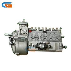
Install injection pumps, fuel injectors, high-pressure fuel lines and fuel filters.
Adjust fuel injection advance angle to achieve accurate injection timing.
4. Intake, Exhaust and Electrical Systems
Fit intake manifolds, air filters, exhaust manifolds, EGR valves and related components.
Install electrical accessories: alternator, starter motor, V-belts, wiring harnesses, etc.
VI. Cylinder Head and Valve Train Assembly
1. Cylinder Head Installation
Place the cylinder head gasket in the correct orientation, lift and mount the cylinder head, then tighten head bolts symmetrically in 2–3 stages.
Tighten aluminum cylinder heads in cold state; cast iron cylinder heads require retightening after hot testing.
2. Rocker Arm and Valve Mechanism Installation
Fit tappets, pushrods and complete rocker arm shaft assemblies.
Adjust valve clearances to specified values under cold conditions, and recheck timing mark alignment.
VII. Final Assembly and Testing
1. Accessory Fitting and Leakage Inspection
Install breathers, oil dipstick tubes, cylinder head covers and other finishing parts.
Carry out air tightness and lubrication system leak tests to eliminate oil, water and air leaks.
2. Fluid Filling and Startup Preparation
Fill engine oil to the specified level, top up coolant, and inspect battery connections.
3. Cold Running-in and Hot Test Run
Cold running-in: Drive the engine via an external electric motor for 1–2 hours to complete preliminary running-in of friction pairs.
Hot test: Ignite and start the engine, gradually raise speed and apply loads, monitor normal parameters including oil pressure, water temperature and exhaust color.
4. Visual Inspection and Factory Acceptance Check
Verify full assembly completeness and ensure all marks and serial numbers are legible for traceability.
Complete data logging and upload records to the quality traceability system.